PART 2
Review
In General:
We will develop parts
For the MSI based
design of Part 3
Review.VHDL
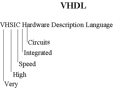
- 1987 IEEE standard
- A language for simulation
- Synthesis
- Hardware test and test application
- Automatic hardware generation
- Timing analysis
Review.levels_of_abstraction
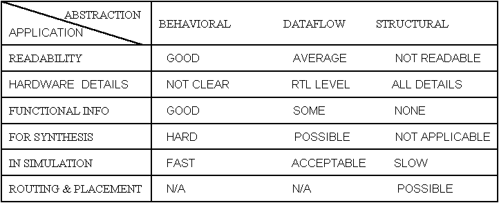

- Levels of abstraction
- Levels of details in hardware description
- Behavioral, the most abstract
- Dataflow, describes bus and register connection
- Structural, wiring and interconnection specification
Review.entity_and_architecture
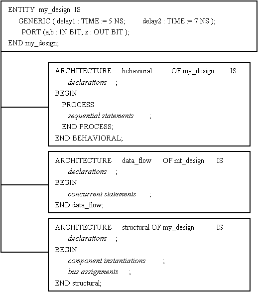
- A hardware component is described by ENTITY and ARCHITECTURE
- Entity for Interface
- Architecture for operation
- Many Architectures can coexist for an Entity
Review.signal_assignments
target <= expr AFTER time;
target <= expr1 WHEN time1 ELSE
expr2 WHEN time2 ELSE
expr3 WHEN time3 ELSE
expr4;
WITH expr SELECT
target <= expr1 WHEN choice1,
expr2 WHEN choice2,
expr3 WHEN choice3,
expr4 WHEN OTHERS;
- Signal assignments are concurrent statements
- Simple, conditional, and selected
- The first type can also be used in sequential bodies
Review.signal_assignments
USE WORK.q_utilities.ALL;
ENTITY and2 IS
PORT (i1, i2 : IN qit; o1 : OUT qit);
END and2;
--
ARCHITECTURE fixed_delay OF and2 IS
CONSTANT prop_delay : TIME := 6 NS;
BEGIN
o1 <= i1 AND i2 AFTER prop_delay;
END fixed_delay;
- Two input NAND gate
- An example of signal assignment is shown
- A constant declaration is used for delay specification
Review.block_statement
label : BLOCK ( guard_condition ) BEGIN
target1 <= GUARDED waveform1 AFTER m1 NS;
target2 <= GUARDED waveform2 AFTER m2 NS;
END BLOCK label;
- Block statement is a concurrent statement
- Guarded signal assignments occur only when condition is TRUE
- Can nest Block statements
Review.block_statement
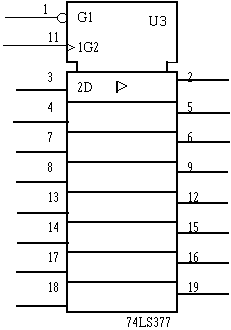
- Rising edge trigger octal register
- Active low enable input
Review.block_statement
USE WORK.q_utilities.ALL;
--
ENTITY ls377 IS
PORT ( clk, g_bar : IN qit;
d8 : IN qit_vector(7 DOWNTO 0) := "ZZZZZZZZ";
q8 : OUT qit_vector(7 DOWNTO 0) := "ZZZZZZZZ" );
END ls377;
--
ARCHITECTURE dataflow OF ls377 IS
CONSTANT prop_delay : TIME := 7 NS;
BEGIN
clocking : BLOCK ( NOT clk'STABLE AND clk = '1' AND ( g_bar = '0' ) )
BEGIN
q8 <= GUARDED d8 AFTER prop_delay;
END BLOCK clocking;
END dataflow;
- Using Block statement for description of 74LS377 octal register
- Clock edge and gating input from the guard condition
Review.bussing
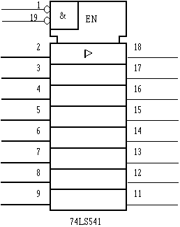
- Octal three-state buffer
- Has two active low gating inputs
Review.bussing
USE WORK.q_utilities.ALL;
--
ENTITY ls541 IS
PORT ( g_bar : IN qit_vector(1 DOWNTO 0);
a8 : IN qit_vector(7 DOWNTO 0) := "ZZZZZZZZ";
y8 : OUT qit_vector(7 DOWNTO 0) := "ZZZZZZZZ");
END ls541;
--
ARCHITECTURE dataflow OF ls541 IS
CONSTANT prop_delay : TIME := 7 NS;
BEGIN
y8 <= a8 AFTER prop_delay WHEN g_bar = "00" ELSE "ZZZZZZZZ";
END dataflow;
- Can use signal assignments for specification of bussing
- Example shows VHDL model for 74LS541
- y8 is normally float
Review.process_statement
label : PROCESS ( sensitivity_list )
VARIABLE : var : qit;
BEGIN
IF condition1 THEN action1;
ELSIF condition2 THEN action2;
ELSE action3;
END IF;
. . .
CASE expression IS
WHEN choice1 => action1;
WHEN choice2 => action2;
WHEN OTHERS => action9;
END CASE;
. . .
END PROCESS label;
- A process statement is a concurrent statement
- Inside a process statement is sequential
- Sequential statements include:
Signal and variable assignments
Loop statements
IF_then_else statements
Case statements
Review.process_statement

- Four bit binary adder
- Uses a carry in and a carry out
Review.process_statement
USE WORK.q_utilities.ALL;
--
ENTITY ls283 IS
PORT ( c0 : IN qit;
c4 : OUT qit;
a4, b4 : IN qit_vector( 3 DOWNTO 0 );
s4 : OUT qit_vector( 3 DOWNTO 0 ) );
END ls283;
--
ARCHITECTURE behavioral OF ls283 IS
CONSTANT prop_delay_c : TIME := 5 NS;
CONSTANT prop_delay_s : TIME := 12 NS;
BEGIN
adder : PROCESS ( a4, b4, c0 )
VARIABLE atemp, btemp, ytemp : INTEGER := 0;
VARIABLE stemp : qit_vector(3 DOWNTO 0) := "0000";
BEGIN
qit2int (a4, atemp);
qit2int (b4, btemp);
IF (c0 = '1') THEN
ytemp := atemp + btemp + 1;
ELSE
ytemp := atemp + btemp;
END IF;
IF ytemp > 15 THEN
c4 <= '1' AFTER prop_delay_c;
ELSE
c4 <= '0' AFTER prop_delay_c;
END IF;
int2qit (ytemp,stemp);
s4 <= stemp AFTER prop_delay_s;
END PROCESS adder;
END behavioral;
- A process statement is used for describing 74LS283
- Procedures are used for type conversion
- Procedure and types are defined in a package
Review.process_statement

- Shift register with parallel load, serial right and left shift
- s=01 right shifts, s=10 left shifts, s=11 loads parallel data
- When g_bar=00 data lines are used as output
Review.process_statement
USE WORK.q_utilities.ALL;
--
ENTITY LS299 IS
PORT ( clk, clr_bar, lin, rin : IN qit;
mode1, mode0 : IN qit := '1';
g_bar : IN qit_vector( 1 DOWNTO 0 ) := "11";
qh, qa : OUT qit;
qq : INOUT wired_qit_vector( 7 DOWNTO 0 ) := "ZZZZZZZZ" );
END LS299;
--
ARCHITECTURE behavioral OF LS299 IS
SIGNAL iq : qit_vector(7 DOWNTO 0) := "ZZZZZZZZ";
CONSTANT prop_delay : TIME := 9 NS;
BEGIN
clocking : PROCESS (clk, clr_bar)
VARIABLE mode : qit_vector (1 DOWNTO 0);
BEGIN
mode := mode1 & mode0;
IF clr_bar = '0' THEN
iq <= "00000000";
ELSE
IF (clk'EVENT AND clk = '1') THEN
CASE mode IS
WHEN "01" => iq <= rin & iq (7 DOWNTO 1);
WHEN "10" => iq <= iq (6 DOWNTO 0) & lin;
WHEN "11" => iq <= qit_vector(qq);
WHEN OTHERS => NULL;
END CASE;
END IF;
END IF;
END PROCESS clocking;
tri_state: PROCESS (iq, g_bar, mode1, mode0)
VARIABLE mode : qit_vector (1 DOWNTO 0);
BEGIN
mode := mode1 & mode0;
IF ( ( g_bar = "00" ) AND ( mode /= "11" ) THEN
qq <= wired_qit_vector(iq) AFTER prop_delay;
ELSE
qq <= "ZZZZZZZZ";
END IF;
END PROCESS tri_state;
qa <= iq(7);
qh <= iq(0);
END behavioral;
- 74LS299 uses a process for its sequential part
- Another process is used for its input/output bussing
Review.process_statement
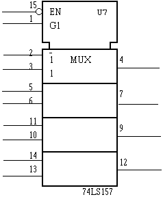
- Four bit 2_to_1 multiplexer
- Enabled only when g_bar is zero
Review.process_statement
USE WORK.q_utilities.ALL;
--
ENTITY ls157 IS
PORT ( g_bar, s : IN qit;
a4, b4 : IN qit_vector( 3 DOWNTO 0 );
y4 : OUT qit_vector( 3 DOWNTO 0 ) );
END ls157;
--
ARCHITECTURE dataflow OF ls157 IS
CONSTANT prop_delay : TIME := 7 NS;
BEGIN
PROCESS ( a4, b4, g_bar, s )
BEGIN
IF g_bar = '0' THEN
IF s = '0' THEN
y4 <= a4 AFTER prop_delay;
ELSE
y4 <= b4 AFTER prop_delay;
END IF;
ELSE
y4 <= "0000";
END IF;
END PROCESS;
END dataflow;
- A process statement is used for multiplexing
- Select a or b based on values of s
- Could use a conditional signal assignment
Review.package
PACKAGE q_utilities IS
TYPE qit IS ('0', '1', 'Z', 'X');
TYPE qit_vector IS ARRAY (NATURAL RANGE<>) OF qit;
TYPE qit_1d IS ARRAY (qit) OF qit;
TYPE qit_2d IS ARRAY (qit, qit) OF qit;
PROCEDURE qit2int (qin:IN qit_vector; int: OUT INTEGER);
PROCEDURE int2qit (int:IN INTEGER; qin: OUT qit_vector);
FUNCTION "AND" (a,b : qit) RETURN qit;
FUNCTION "NOT" (a : qit) RETURN qit;
FUNCTION bit2qit(bit_in : bit_vector) RETURN qit_vector;
FUNCTION wire (a, b : qit) RETURN qit;
FUNCTION wiring (drivers : qit_vector) RETURN qit;
SUBTYPE wired_qit IS wiring qit;
TYPE wired_qit_vector IS ARRAY (NATURAL RANGE <>) OF wired_qit;
END q_utilities;
- Use packages for packaging parts and utilities
- Package declaration declares all visible entries
- The use statement makes a package visible
- Contains all utilities used in previous descriptions
Review.package
PACKAGE BODY q_utilities IS
PROCEDURE qit2int (qin:IN qit_vector; int:OUT INTEGER) IS
VARIABLE result: INTEGER;
BEGIN result := 0;
FOR i IN 0 to (qin'LENGTH -1) LOOP
IF qin(i) = '1' THEN result := result + 2**i; END IF;
END LOOP; int := result;
END qit2int;
PROCEDURE int2qit (int:IN INTEGER; qin:OUT qit_vector) IS
VARIABLE tmp : INTEGER;
BEGIN tmp := int;
FOR i IN 0 TO (qin'LENGTH - 1) LOOP
IF (tmp MOD 2 = 1) THEN qin (i) := '1'; ELSE qin (i) := '0'; END IF;
tmp := tmp / 2;
END LOOP;
END int2qit;
FUNCTION bit2qit (bit_in : bit_vector) RETURN qit_vector IS
VARIABLE qit_out : qit_vector (bit_in'RANGE);
BEGIN
FOR i IN bit_in'RANGE LOOP
IF bit_in(i) ='1' THEN qit_out(i) := '1'; ELSE qit_out(i) := '0'; END IF;
END LOOP;
RETURN qit_out;
END bit2qit;
FUNCTION "AND" (a,b : qit) RETURN qit IS
CONSTANT qit_and_table : qit_2d := ( ('0','0','0','0') ,
('0','1','1','X') ,
('0','1','1','X') ,
('0','X','X','X') );
BEGIN RETURN qit_and_table (a,b);
END "AND";
FUNCTION "NOT" (a : qit) RETURN qit IS
CONSTANT qit_not_table : qit_1d := ('1','0','0','X');
BEGIN RETURN qit_not_table (a);
END "NOT";
FUNCTION wire (a, b : qit) RETURN qit IS
CONSTANT qit_wire_table : qit_2d := ( ('0','0','0','X') ,
('0','1','1','X') ,
('0','1','Z','X') ,
('X','X','X','X') );
BEGIN RETURN qit_wire_table (a, b);
END wire;
FUNCTION wiring (drivers : qit_vector) RETURN qit IS
VARIABLE accumulate : qit := 'Z';
BEGIN
FOR i IN drivers'RANGE LOOP
accumulate := wire (accumulate, drivers(i));
END LOOP;
RETURN accumulate;
END wiring;
END q_utilities;
- Type conversions, overloading, resolutions
Review.using_MSI_parts
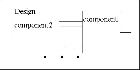
- A complete design contains wiring of library parts
- Component instantiations are used for wiring such parts
- An MSI based design uses 7400 series described here
Review.conclusions
1. Outline: Introduction, Organization, Outline
3. MSI Based Design: Use MSI parts of Part 2, Sequential multiplication, Designing the multiplier, Control and data parts, Testing the multiplier
4. General CPU Description: Will present a high level VHDL description of a small CPU. The CPU, Memory organization, Instructions, Addressing, Utilities for VHDL description, Interface, Behavioral description, Coding individual instructions
5. Manual Data_path Design: Will present VHDL description for manual design of data_path. Data components, Bussing structure, Description of logic, Description of registers, Bus resolutions, Component wiring
6. Manual Controller Design: Will present VHDL description for manual design of controller. Controller hardware, VHDL style, Signals and resolutions, State descriptions, Complete CPU, Testing CPU
7. Synthesis: Main concepts, Structural synthesis, Combinational circuits, Functional registers, State machines
8. Behavioral_Synthesis: Will present a high level synthesizable CPU description. Synthesis style, Necessary Package, Interface, General Layout, Registers, Clocking, Sequencing, Simulation and Synthesis
9. Dataflow_Synthesis: Will partition the CPU and synthesize each part separately. Synthesis style, Controller, Data components, Data path, Synthesized example, Conclusions
to the top of the Document


