Project: Build a circuit to play Black Jack.
Nov. 6, 2003
EE481 Logical Design Lab
Fall 2003, Project
Prof. Michael E. Lhamon
Experiments
- You may use whatever technology you choose to implement your
design, discrete logic gates, PALs, CPLD's or any combination thereof. (Be sure to use drop resistors in series with the LED's and LED display.)

- Inputs to the circuit will be Clock, Start, Hit, and Stand. Start, Hit, and Stand
are user inputs via a debouced push buttons. You are allowed to use
additional clocks if necessary. ( Hint: multiplexing the LED display
saves pins but require an additional clock.)
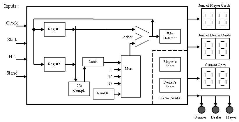
- Outputs will have a
minimum of two 7-segment LED displays and three LED's. (You can be
creative on implementation..) The information shown above is what
must to conveyed to the user in all designs..
- The architecture shown above is one possible implementation. Hint:
What is the use of "0", "10" and "17" inputs to the mux?
- The card drawn must come from a random number generator and assume
the deck of cards is infinite. Hint: You can design a counter that
sequences 1 through 10 which is clocked from a high speed source or you can
use an additional input non-debounced to drive the clock to the
1-10 counter.
- Ace's count as 1 or 11 but to simplify the design you can assume that any one player cannot have more than one Ace.
- Hints are not necessary to follow.
- CPLD's have an IC count of 3, PLD's have an IC count of 2.
Use a minimal number of IC's in your design to obtain maximum credit.
- The
static current consumption for your digital circuit without LED's and clocks
will be measured. Lowest current obtains maximum credit.
- A working design is worth more credit then a sub optimal design which doesn't work.
- Player's and Dealers score displays are for extra credit points.
- Be sure to read your PALASM and ABEL (Design Direct) documentation
on software syntax to minimize your design effort and to maximize your success.
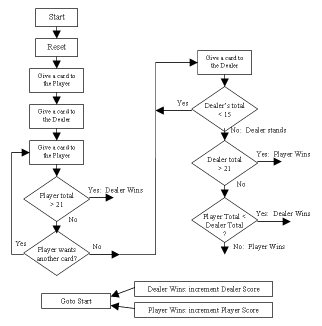
- The operational flow chart below is how every design needs to operate.
Notice that is only covers user and machine interactions.
- More info to follow.

ee481


