Logic Synthesis with VHDL
System Synthesis
Bob Reese
Electrical Engineering Department
Mississippi State University
Converted to HTML by
MANJUNATH R. MITTHA
MS Student, Dept. of Elec. Eng.,
Mississippi State University
Index
VHDL Packages
Example VHDL Package
VHDL Functions
VHDL Procedures
Signals vs. Variables
Using the Ripple_Adder Procedure
A Carry Select Adder
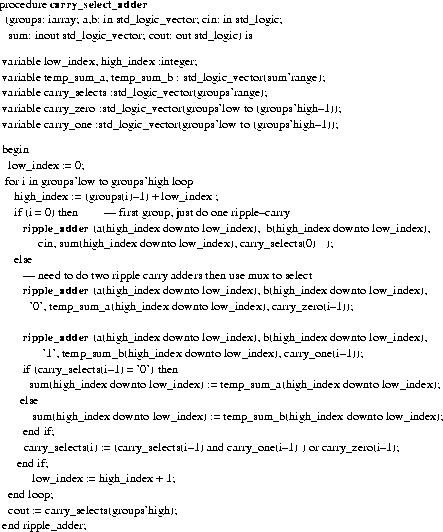
Carry_Select_Adder Procedure
iscas Package Declaration
Using the Carry_Select_Adder Procedure
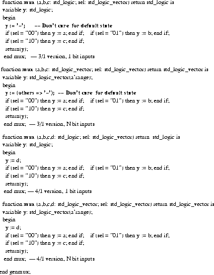
VHDL Generic Lists
Operator Overloading
Test of 'MUX' Function
BlackJack Dealer
BlackJack Dealer Control
BlackJack Datapath
VHDL File for BlackJack Datapath
VHDL File for BlackJack Control
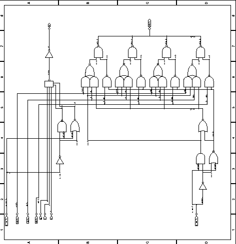
Top Level Schematic for Dealer
BlackJack Dealer Simulation
Structural VHDL
Structural VHDL for BlackJack Player
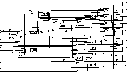
Results of bj_struct Synthesis
- A VDHL package is a mechanism for collecting procedures, functions, constants, and components
for future re-use.
- A package contains a package declaration followed by a package body.
- Package declaration
package package_name is
{ external constant, procedure, function,
component declarations }
end package_name;
- Package body
package body package_name is
{constant, procedure, function, component
definitions }
end package_name;
Any items in the package declaration are available for external use. There can be items in the
package body which are not in the package declaration; these items are only available for use
within the package.
BACK TO INDEX

BACK TO INDEX
General form:
function function_name ( parameter list) return return_type is
{variable declarations}
begin
{sequential statements}
end function_name;
function xor3 (a,b,c: in std_logic) return std_logic is
begin
return (a xor b xor c);
end xor3;
A VHDL function computes a return value based upon its parameter list.
- All parameters passed to a VHDL function must be of mode in; i.e, the function is not
allowed to modify any of the function parameters.
- The default class of the elements in a parameter list for either procedures or functions
is variable.
- Signals can be passed in the parameter list; in this case the parameter list would look like:
(signal a, b, c: std_logic)
- More on the difference between variables and signals will be given later.
BACK TO INDEX
General form:
procedure procedure_name ( parameter list) is
{variable declarations}
begin
{sequential statements}
end procedure_name;
The ripple_adder procedure implements the ripple carry adder used in previous examples.
The ripple_adder procedure uses the local xor3 function defined within the package.
sum(i+sum'low) := xor3 (a(i+a'low), b(i+b'low), c(i) );
For generality, the input parameters 'a' and 'b' as well as the output 'sum' are declared as
unconstrained array types; i.e., no array bounds are given for the std_logic_vector type.
- Allows any width vector to be passed as a parameter.
- Array indices must be computed using the 'low attribute as an offset in order to
achieve independence from the actual array indices which are passed in.
BACK TO INDEX
- Only signals are used as the connection ports for VHDL entities.
- Variables are declared within process blocks, procedures, and functions.
- Signals can only be declared within architecture bodies; they can be passed as
parameters to functions and procedures.
- Signals are assigned via "<="; Variables are assigned via ":=".
- From a simulation point of view:
- Signals have events occurring on them and this event history is tracked via an
internal event list.
- Signal assignment can be delayed such as:
a <= '1' after 10 ns
- Variable assignment is always immediate.
a <= '1';
- Signals require more overhead in terms of storage and simulation time than
variables. A general rule of thumb is to use variables wherever possible.
- From a synthesis point of view, both variables and signals can turn into internal circuit nodes.
BACK TO INDEX

BACK TO INDEX

BACK TO INDEX

BACK TO INDEX
Library IEEE;
use IEEE.std_logic_1164.all;

package iscas is

 type IARRAY is array (natural range <>) of integer;

 procedure ripple_adder (a,b: in std_logic_vector; cin: in std_logic;
                          sum: inout std_logic_vector; cout: out std_logic);

procedure carry_select_adder
	     (groups: iarray; a,b: in std_logic_vector;  cin: in std_logic;
                        sum: inout std_logic_vector; cout: out std_logic);
end iscas;
- We need to declare an array type for integers; call this IARRAY. This type will be used to pass
in an integer array to the carry_select_adder procedure; the integer array will be define the
stage sizes for the adder.
- Since xor3 is to be local to the iscas package; it is not in the package declaration. However, if
it was to be made externally available, its declaration would be:
function xor3 (a,b,c: in std_logic) return std_logic;
BACK TO INDEX


BACK TO INDEX

- VHDL generic lists are used in entity declarations for passing static information.
- Typical uses of generics are for controlling bus widths, feature inclusion, message
generation, timing values.
- A generic will usually have a specified default value; this value can be overridden via VHDL
configurations or by vendor-specific back-annotation methods.
- Generics offer a method for parameterizing entity declarations and architectures. Because
the method of specifying generic values (other than defaults) can be vendor specific,
generics will not be covered further in this tutorial.
BACK TO INDEX


BACK TO INDEX


BACK TO INDEX
- This example will be a BlackJack Dealer circuit (example taken from The Art of Digital
Design, Prosser & Winkel, Prentice-Hall).
- One VHDL model will be written for the control and one for the datapath. A schematic
will be used to tie these two blocks together.
- Later, a VHDL structural model will be used to connect the blocks.
- Control:
- Four States:
Get -- get a card
Add -- add current card to score
Use -- use an ACE card as 11
Test -- see if we should stand or if we are broke
Datapath:
- 5-bit register for loading score; needs a synchronous clear.
- Mux for choosing between card value, plus 10 and minus 10.
- Adder for adding card with current score.
- ACE card detect (an ACE card has value '0001')
- Comparator logic for checking is score is greater than 16 or greater than 21.
BACK TO INDEX


BACK TO INDEX
BlackJack Datapath

BACK TO INDEX

BACK TO INDEX


BACK TO INDEX


BACK TO INDEX

BACK TO INDEX


BACK TO INDEX
- You do not have to use a schematic to connect VHDL blocks. You can write a structural
VHDL model which ties the blocks together.
- Pros:
- When you synthesize the design all of the VHDL blocks are flattened (collapsed into
one block) and it is possible that the resulting logic may be more efficient.
- The structural VHDL code is more portable to other design systems than a schematic.
- Cons:
- Writing structural VHDL code can be more error prone than creating a schematic
(very easy to misplace a net when you don't have a 'picture' to go by).
- The resulting flattened netlist can be more difficult to debug.
BACK TO INDEX


BACK TO INDEX

BACK TO INDEX


